3. ∞Ó Ë ·ÓÙ›ÛÙ·ÛË Ô˘ ÚfiÎÂÈÙ·È Ó· ÌÂÙÚËı› ›ӷÈ
Û˘Ó‰Â‰Â̤ÓË Û ·Îψ̷, ı· Ú¤ÂÈ Ó·
‰È·Îfi„ÂÙ ÙËÓ Ù¿ÛË Î·È Ó· ÊÚÔÓÙ›ÛÂÙ ÒÛÙ ӷ
ÂÎÊÔÚÙˆıÔ‡Ó fiÏÔÈ ÔÈ ˘ÎÓˆÙ¤˜ ÚÈÓ ·Ú¯›ÛÂÙÂ
ÙË Ì¤ÙÚËÛË.
10.5 ª¤ÙÚËÛË ‰Èfi‰ˆÓ (Ù¿ÛË Î·Ù¿ÛÙ·Û˘
·ÁˆÁ‹˜)
1. ™˘Ó‰¤ÛÙ ÙÔ ª∞Àƒ√ ηÏÒ‰ÈÔ ÛÙËÓ ˘Ô‰Ô¯‹
“COM” Î·È ÙÔ ∫√∫∫π¡√ ηÏÒ‰ÈÔ ÛÙËÓ
˘Ô‰Ô¯‹ “V mA”. (Àfi‰ÂÈÍË: ∏ ÔÏÈÎfiÙËÙ· ÙÔ˘
ÎfiÎÎÈÓÔ˘ ηψ‰›Ô˘ Â›Ó·È “+”.)
2. ƒ˘ıÌ›ÛÙ ÙÔÓ ‰È·ÎfiÙË FUNCTION ÛÙËÓ
ÂÚÈÔ¯‹ Î·È Û˘Ó‰¤ÛÙ ÙȘ ·Î›‰Â˜ ̤ÙÚËÛ˘
ÛÙË ‰›Ô‰Ô Ô˘ ı¤ÏÂÙ ӷ ÌÂÙÚ‹ÛÂÙÂ. ∫·Ù¿ ÙË
̤ÙÚËÛË ‰Èfi‰ˆÓ ‹ ÙÚ·Ó˙›ÛÙÔÚ, Ë ÔÏÈÎfiÙËÙ·
ÙˆÓ ·Î›‰ˆÓ ̤ÙÚËÛ˘ ηıÔÚ›˙ÂÈ ·Ó ÌÂÙÚÈ¤Ù·È Ë
ÂÌÚfiÛıÈ· ηÙ‡ı˘ÓÛË ‹ Ë Î·Ù‡ı˘ÓÛË
·ÔÎÏÂÈÛÌÔ‡. ∏ ÙÈÌ‹ Ô˘ Ê·›ÓÂÙ·È ÛÙËÓ ÔıfiÓË
Â›Ó·È Ë ÙÒÛË Ù¿Û˘ ÛÙËÓ Î·Ù¿ÛÙ·ÛË ·ÁˆÁ‹˜.
- ∏ ÈÛ¯‡˜ ·ÂÌÏÔ΋˜ Â›Ó·È 0.8 mA.
- ∞Ó ÔÈ ·Î›‰Â˜ ̤ÙÚËÛ˘ ‰ÂÓ Â›Ó·È Û˘Ó‰Â‰Â̤Ó˜
(ÛˆÛÙ¿) ÛÙË ‰›Ô‰Ô, .¯. ÚÔ˜ ÙËÓ Î·Ù‡ı˘ÓÛË
·ÔÎÏÂÈÛÌÔ‡, Ë ÔıfiÓË ı· ‰Â›¯ÓÂÈ ÙÔÓ ·ÚÈıÌfi 1.
10.6 ª¤ÙÚËÛË ÙÚ·Ó˙›ÛÙÔÚ hFE
1. ∞Ê·ÈÚ¤ÛÙ ÙÔ Î·ÏÒ‰ÈÔ Ì¤ÙÚËÛ˘.
2. µ¿ÏÙ ÙÔÓ ‰È·ÎfiÙË ÛÙË Ú‡ıÌÈÛË hFE.
3. ∂ϤÁÍÙ ·Ó ÙÔ Û˘ÁÎÂÎÚÈ̤ÓÔ ÙÚ·Ó˙›ÛÙÔÚ Â›Ó·È
Ù‡Ô˘ NPN ‹ PNP Î·È Û˘Ó‰¤ÛÙ ÙÔ Î·ÏÒ‰ÈÔ
ÙÔ˘ ÂÎÔÌÔ‡ (e), Ù˘ ‚¿Û˘ (b) Î·È ÙÔ˘
Û˘ÏϤÎÙË (c ) ÛÙËÓ Î·Ù¿ÏÏËÏË ˘Ô‰Ô¯‹ ÛÙÔÓ
›Ó·Î· Ô˘ ‚Ú›ÛÎÂÙ·È ÛÙÔ ÂÌÚfi˜ ̤ÚÔ˜.
4. ∏ ÔıfiÓË ‰Â›¯ÓÂÈ (ηٿ ÚÔÛ¤ÁÁÈÛË) ÙËÓ ÙÈÌ‹
hFE ÁÈ· ¤Ó· ‚·ÛÈÎfi Ú‡̷ 10 mA, V CE 2.8 V.
11. ™À¡∆∏ƒ∏™∏
¶ƒ√™√Ã∏
ñ £· Ú¤ÂÈ ¿ÓÙÔÙ ӷ ‚Á¿˙ÂÙ ÙËÓ Ì·Ù·Ú›·
ÚÈÓ ·fi ÙË Û˘ÓÙ‹ÚËÛË Î·È ÙÔÓ Î·ı·ÚÈÛÌfi ÙÔ˘
ÔÏ˘Ì¤ÙÚÔ˘. ªË ¯ÚËÛÈÌÔÔț٠ÔÙ¤ ÓÂÚfi ‹
¿ÏÏ· ˘ÁÚ¿ ÁÈ· ÙÔÓ Î·ı·ÚÈÛÌfi Ù˘ Û˘Û΢‹˜.
ñ ¢È·ÙËÚ›Ù ٷ ηÏ҉ȷ ̤ÙÚËÛ˘ Î·È ÙÔ
ÔχÌÂÙÚÔ Î·ı·Ú¿. √ÚÈṲ̂ӷ ̤۷
ηı·ÚÈÛÌÔ‡ ‹ ‰È·Ï‡Ù˜ (ÂÙڤϷÈÔ, ·Ú·ÈˆÙÈο
Î.Ï.) ÌÔÚ› Ó· ÚÔÛ‚¿ÏÔ˘Ó ‹ Ó· ‰È·Ï‡ÛÔ˘Ó
Ù· Ï·ÛÙÈο ̤ÚË. ∞˘Ù¿ Ù· ÚÔ˚fiÓÙ·
ÂÚȤ¯Ô˘Ó ‚ÂÓ˙fiÏÈÔ, ÙÚȯψÚÔ·Èı¿ÓÈÔ,
¯ÏÒÚÈÔ, ˘ÁÚ‹ ·Ì̈ӛ· Î.Ï.
ñ ∫·ı·Ú›˙ÂÙ ٷÎÙÈο ÙÔ ÂÚ›‚ÏËÌ· Ì ¤Ó·
Ì·Ï·Îfi ·Ó›, ηٿ ÚÔÙ›ÌËÛË ÌÂÙ¿ ·fi οıÂ
¯Ú‹ÛË.
ñ ∞Ê·ÈÚ¤ÛÙ ÙȘ ›ÌÔÓ˜ ‚ÚÔÌȤ˜ Ì ¤Ó· ˘ÁÚfi
·Ó›. ªË ¯ÚËÛÈÌÔÔț٠‰È·Ï‡Ù˜ fiˆ˜
ÂÙڤϷÈÔ, ÔÈÓfiÓÂ˘Ì·, ‰È¿Ï˘Ì· ·Ì̈ӛ·˜
Î.Ï. ∞˘Ù¿ Ù· ˘ÁÚ¿ ÚÔηÏÔ‡Ó ˙ËÌÈ¿ ÛÙ·
Ï·ÛÙÈο ̤ÚË Ù˘ Û˘Û΢‹˜.
12. ¶ƒ√µ§∏ª∞∆∞
∞Ó ÙÔ ÔχÌÂÙÚÔ ‰ÂÓ ÏÂÈÙÔ˘ÚÁ› ÛˆÛÙ¿, ÔÈ ·Èٛ˜
ÌÔÚ› Ó· Â›Ó·È ÔÈ ÂÍ‹˜:
1. ∆Ô ÔχÌÂÙÚÔ ‰ÂÓ ‰Â›¯ÓÂÈ Ù›ÔÙ· ÛÙËÓ ÔıfiÓË.
ñ ∏ Ì·Ù·Ú›· Â›Ó·È ¿‰ÂÈ·.
- ∞ÓÙÈηٷÛÙ‹ÛÙ ÙËÓ Ì·Ù·Ú›·.
ñ ∆Ô Ú‡̷ ‹ Ë Ù¿ÛË Ô˘ ÌÂÙÚ‹ıËΠ‹Ù·Ó
˘ÂÚ‚ÔÏÈο ˘„ËÏ‹, Ì ·ÔÙ¤ÏÂÛÌ· ÙÔ
ÔχÌÂÙÚÔ Ó· ˘ÔÛÙ› ‚Ï¿‚Ë, ·Ú¿ ÙȘ
‰È·Ù¿ÍÂȘ ·ÛÊ·Ï›·˜.
- ™Â ÂÚ›ÙˆÛË ÚÔ‚Ï‹Ì·ÙÔ˜,
ÂÈÎÔÈÓˆÓ‹ÛÙ Ì ÙÔ ÙÔÈÎfi ΤÓÙÚÔ
Ù¯ÓÈ΋˜ ˘ÔÛÙ‹ÚÈ͢.
2. ∆Ô ÔχÌÂÙÚÔ ‰ÂÓ ‰Â›¯ÓÂÈ Î·Ì›· ÌÂÙÚÔ‡ÌÂÓË
ÙÈÌ‹.
ñ Œ¯ÂÈ Î·Â› Ë ·ÛÊ¿ÏÂÈ·.
- ∞ÓÙÈηٷÛÙ‹ÛÙ ÙËÓ ·ÛÊ¿ÏÂÈ·.
ñ ŒÓ· ‹ ÂÚÈÛÛfiÙÂÚ· ·fi Ù· ηÏ҉ȷ ›ӷÈ
ÂÏ·Ùو̷ÙÈο.
- ∞ÓÙÈηٷÛÙ‹ÛÙ ٷ ηÏ҉ȷ ̤ÙÚËÛ˘.
ñ ∆Ô Ú‡̷ ‹ Ë Ù¿ÛË Ô˘ ÌÂÙÚ‹ıËΠ‹Ù·Ó
˘ÂÚ‚ÔÏÈο ˘„ËÏ‹, Ì ·ÔÙ¤ÏÂÛÌ· ÙÔ
ÔχÌÂÙÚÔ Ó· ˘ÔÛÙ› ‚Ï¿‚Ë, ·Ú¿ ÙȘ
‰È·Ù¿ÍÂȘ ·ÛÊ·Ï›·˜.
- ™Â ÂÚ›ÙˆÛË ÚÔ‚Ï‹Ì·ÙÔ˜,
ÂÈÎÔÈÓˆÓ‹ÛÙ Ì ÙÔ ÙÔÈÎfi ΤÓÙÚÔ
Ù¯ÓÈ΋˜ ˘ÔÛÙ‹ÚÈ͢.
∞¡∆π∫∞∆∞™∆∞™∏ ∆∏™ ∞™º∞§∂π∞™
1. µ¿ÏÙ ÙÔÓ ‰È·ÎfiÙË ÛÙË Ú‡ıÌÈÛË OFF.
2. ∞Ê·ÈÚ¤ÛÙ ÙÔ ›Ûˆ Î¿Ï˘ÌÌ· ÙÔ˘ ÔÏ˘Ì¤ÙÚÔ˘
Í‚ȉÒÓÔÓÙ·˜ ÙȘ ‚›‰Â˜.
¶ƒ√™√Ã∏! ∏ Û˘Û΢‹ ı· Ú¤ÂÈ Ó·
ÙÂı› ÂÎÙfi˜ ÏÂÈÙÔ˘ÚÁ›·˜ Î·È Ù· ηÏ҉ȷ
ı· Ú¤ÂÈ Ó· ·Ê·ÈÚÂıÔ‡Ó ÚÈÓ ·ÓÔ›ÍÂÙÂ
ÙÔ ÂÚ›‚ÏËÌ· ÙÔ˘ ÔÏ˘Ì¤ÙÚÔ˘.
3. ∞Ê·ÈÚ¤ÛÙ ÙËÓ ÂÏ·Ùو̷ÙÈ΋ ·ÛÊ¿ÏÂÈ· ηÈ
·ÓÙÈηٷÛÙ‹ÛÙ ÙËÓ Ì ÌÈ· ·ÛÊ¿ÏÂÈ· Ù˘ ›‰È·˜
ÈÛ¯‡Ô˜ Î·È Ì ÙȘ ›‰È˜ ȉÈfiÙËÙ˜ ‰È·ÎÔ‹˜ (250
V~ F200mAL).
13. §§∞°∏ ∆∏™ ª¶∞∆∞ƒπ∞™
1. ∆Ô Û‡Ì‚ÔÏÔ Ù˘ Ì·Ù·Ú›·˜ ı· ÂÌÊ·ÓÈÛÙ› ÛÙËÓ
ÔıfiÓË fiÙ·Ó Ë Ì·Ù·Ú›· Â›Ó·È Û¯Â‰fiÓ ¿‰ÂÈ·.
2. µ¿ÏÙ ÙÔ ÂÚÈÛÙÚÔÊÈÎfi ÎÔ˘Ì› ÛÙË Ú‡ıÌÈÛË
OFF.
3. ∞Ê·ÈÚ¤ÛÙ ÙÔ ›Ûˆ Î¿Ï˘ÌÌ· ÙÔ˘ ÔÏ˘Ì¤ÙÚÔ˘
Í‚ȉÒÓÔÓÙ·˜ ÙȘ ‚›‰Â˜.
¶ƒ√™√Ã∏! ∏ Û˘Û΢‹ ı· Ú¤ÂÈ Ó·
ÙÂı› ÂÎÙfi˜ ÏÂÈÙÔ˘ÚÁ›·˜ Î·È Ù· ηÏ҉ȷ
ı· Ú¤ÂÈ Ó· ·Ê·ÈÚÂıÔ‡Ó ÚÈÓ ·ÓÔ›ÍÂÙÂ
ÙÔ ÂÚ›‚ÏËÌ· ÙÔ˘ ÔÏ˘Ì¤ÙÚÔ˘.
4. ∞ÓÙÈηٷÛÙ‹ÛÙ ÙËÓ Ì·Ù·Ú›· 9 Volt Ì ÌÈ·
ηÈÓÔ‡ÚÁÈ· Ì·Ù·Ú›· Ù‡Ô˘ 6F22, ‹,
ÂÓ·ÏÏ·ÎÙÈο: 6R61 / 6LR61 / 6LF22.
Ferm 81
5. ENVIRONMENTAL PROTECTION
Raw material recovery is better than garbage
disposal. To avoid damages in transport, the device
must be delivered in solid packing made mostly
from recyclable material such as paper, pulp and
wood. We therefore recommend that you recycle
the packing as far as possible.
The multimeter is operated on batteries.
Dispose of spent batteries as stipulated.
For instructions on replacing batteries, refer to
chapter 13 "Changing batteries".
6. AFTER SALES SERVICE
Please retain the original packing. If the device
needs to be transported again, the risk of damage
during transport is minimised if you use the original
packing. If a warranty claim is made, the device
must be sent in as securely packed as possible,
preferably in the original packing. All Ferm products
undergo exhaustive testing before they leave the
factory. Should however a defect be detected in
your device, please contact at your Service address
first.
7. BEFORE PUTTING IN SERVICE
1. In case the voltage and/or the current to be
measured is/are unknown, set the rotary knob
on the largest measuring range. If the accuracy
on the rotary knob is insufficient, set on a lower
range and so on.
2. If the device is not going to be used temporarily,
put the rotary knob in the OFF position.
3. The switching of the multimeter is different for
measuring voltage and for measuring current.
Parallel connection in voltage measurement
and series connection in current measurement.
In the latter case, a conductor in the power circuit
to be measured must be interrupted.
4. Never connect a power source or voltage to the
multimeter, if the FUNCTION switch is in the or
position.
5. Never connect a voltage higher than 600 V DC or
600 V to the measuring device.
8. BRIEF SYNOPSIS FOR
MEASUREMENTS
The multimeter is suitable for measuring:
• Direct voltage (VDC, voltage of accumulator or
battery, for example)
• Direct current (ADC)
• Alternating voltage (VAC, voltage of the mains
input of a device, for example)
• Resistance ( , Ohm)
• Diodes and hFE transistor measurement
A measurement object can be under voltage.
To measure it, connect the multimeter in parallel.
If the current strength is to be measured, include the
multimeter in the circuit (series connection). The
power circuit for measuring the current must
necessarily be isolated, because the current has to
flow through the multimeter.
You must not switch the multimeter on Current
measurement, for example, if you are measuring
the voltage. You could damage the multimeter
beyond repair by causing a short circuit in this case.
9. OPERATION (REFER TO FIGURE 1).
A. 3,5-digit LCD display (max. display: 1999.
Display of decimal point, polarity, overload and
discharged battery indication.
B. FUNCTION switch: Rotary switch for the range
to be set
C. hFE-transistor measuring
D. 10 A. Positive connection for current
measurements over 200 mA up to a maximum
value of 10 A.
E. COM. Negative connection.
F. V mA. Positive connection for voltage and
resistance measurements. Up to 200 mA.
G. Hold button
When this button is pushed, the display will keep
the last reading and "H" symbol will appear on
the LCD until pushing it again.
10. MEASUREMENTS
10.1 Measuring direct voltage (V DC)
1. Connect the BLACK lead to the "COM"
connector socket and the RED lead to the
"V mA" connector socket.
2. Set the FUNCTION switch on the desired "V"
setting and connect the leads to the voltage
source to be measured or measuring points.
Observe correct polarity (red is + and black is -),
otherwise the display shows a minus sign before
the value.
3. Read off the measured value in Volt.
RANGE ACCURACY RES.
Input resistance 10 M
Overload protection DC 600 V or AC 600 V Effective
value
(outside 200-mV-range with highest value of 250 V
Effective value).



Присоединиться к беседе по данному изделию
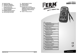
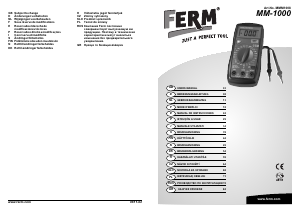
Здесь вы можете поделиться тем, что думаете о FERM MMM1007 Мультиметр. Если у вас есть вопросы, сначала внимательно прочтите инструкцию. Запросить руководство можно с помощью контактной формы.
ответить | Это было полезно (0) (Переведено Google)